
Solar Panel Fire Risks Surge as Cost-Cutting Lamination Practices Drive Record Delamination Failures
Aggressive encapsulant downsizing and the removal of rigid lamination frames have compromised critical creepage distances, leading to documented field fires.
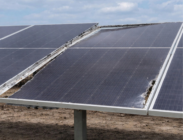
Aggressive material downsizing and the abandonment of proven lamination tooling by solar module manufacturers have triggered a dramatic rise in delamination defects, creating electrical arcing hazards that can ignite rooftop and utility-scale fires.
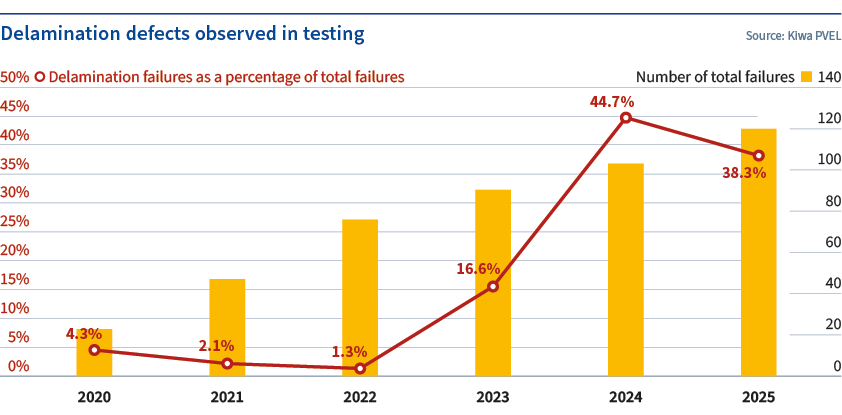
Testing data compiled through 2026 by Kiwa PVEL shows that delamination failures among evaluated bills of materials (BOMs) have escalated from 1.3% in 2022 to 44.7% in 2024. The rate remained elevated at 38.3% for BOMs produced in 2025, with the upward trajectory continuing into 2026. This spike correlates directly with industry-wide efforts to reduce manufacturing costs by trimming encapsulant dimensions and replacing rigid perimeter locking frames with cheaper taping methods during the lamination process.
The consequences extend well beyond cosmetic blemishes or accelerated degradation. When delamination or gas bubbles form along the perimeter of a photovoltaic module, they compromise the electrical creepage distance—the physical gap required to prevent current from jumping between the internal circuit and the aluminum frame. Under IEC 61730 and UL safety qualification standards, a 1,500-volt module requires a minimum creepage distance of 10.4 millimeters. Field investigations by Kiwa PI Berlin have documented instances where edge bubbles breached this threshold, forming a conductive path that resulted in severe electrical arc faulting and subsequent fire.

Standard solar modules operate at system voltages up to 1,500V DC in utility-scale arrays, making adequate insulation spacing non-negotiable. Unlike alternating current, direct current does not naturally cross zero, meaning an established arc will sustain itself indefinitely until the circuit is physically broken or the fuel source is exhausted. This physics reality makes perimeter delamination one of the most dangerous latent defects in modern photovoltaic manufacturing.
Not all polymer chemistries carry equal risk. Testing across dozens of BOMs revealed that modules utilizing EPE—a polyolefin core sandwiched between two ethylene vinyl acetate (EVA) layers—as both the front and rear encapsulant experienced the highest failure rates. More than 30% of the 42 BOMs built with EPE suffered major delamination defects. Modules using polyolefin elastomer (POE) on both sides followed, with a 20% major defect rate across 15 BOMs. Front-side EVA configurations proved the most resilient, though EVA has become the least commonly specified front-side material over the past three years as manufacturers shifted toward POE and EPE for their superior moisture resistance and compatibility with bifacial n-type cells like TOPCon and heterojunction (HJT).
Despite these chemistry-specific trends, the brand or specific model of the encapsulant resin did not dictate outcomes. Identical encapsulant models yielded vastly different results—ranging from zero defects to major delamination—depending on the manufacturer assembling the module. This isolates factory-level assembly practices, rather than raw material sourcing, as the primary variable.
A critical driver of corner and edge failures is the deliberate narrowing of encapsulant sheets relative to the glass substrate. To save material costs, some production lines now cut encapsulant widths at least 6 millimeters smaller than the glass. BOMs employing this aggressive sizing recorded an 18.6% failure rate at the module corners. During lamination, the heated polymer melts and flows outward; if the starting sheet is too narrow, the corners are left starved of sealing material, leaving gaps vulnerable to moisture ingress and mechanical separation.
Counterintuitively, overall encapsulant thickness does not reliably predict failure. An analysis of EPE area weights ranging from 380 grams per square meter to 530 g/m² showed no linear correlation with delamination. The highest concentration of major defects actually occurred at 480 g/m². However, environmental stress testing confirmed that high heat (85°C) combined with high humidity (85% relative humidity) severely exacerbates existing weaknesses. Roughly one-third of all delamination defects manifested only after extended damp heat testing of 1,000 to 2,000 hours, while others appeared during thermal cycling, mechanical stress sequences, potential induced degradation (PID), and ultraviolet induced degradation (UVID) protocols.
The transition away from traditional stiff locking frames during glass-glass module lamination has compounded the dimensional issues. Historically, rigid frames contained the melting encapsulant and prevented edge pinch-out. As throughput demands increased, many factories replaced these frames with adhesive tapes applied along the edges or exclusively at the corners to catch overflow. Corner-only taping methods demonstrated the highest susceptibility to delamination among the alternative techniques tested.
Lamination recipes themselves—specifically temperatures between 140°C and 155°C and cycle times of 400 to 750 seconds—did not correlate with the defect clusters. Because most major failures occurred squarely within these standard processing windows, equipment stability and baseline material quality emerge as the underlying culprits rather than recipe deviations.
Solder flux chemistry represents a distinct, localized failure vector. Five out of 44 flux models tested between 2024 and 2026 caused a specific defect pattern: expanding bubbles originating at string busbar solder joints. Improper flux formulations or inadequate residue cleaning before lamination allows trapped volatiles to vaporize under operating temperatures, forcing the encapsulant away from the cell interconnects.
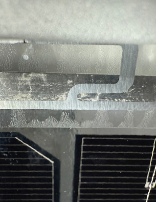 Delamination, label | Image: Kiwa PVEL
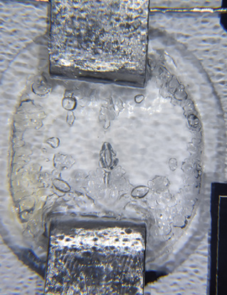 bubbles, junction box | Image: Kiwa PVEL
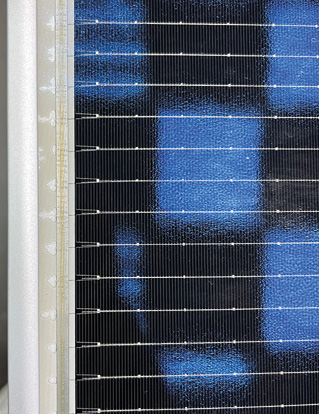 Delamination, edge | Image: Kiwa PVEL
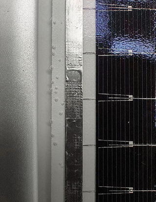 Bubbles, edge | Image: Kiwa PVEL
Procurement teams and independent engineers evaluating module suppliers must now scrutinize factory-level lamination tooling, encapsulant-to-glass dimensional tolerances, and flux cleaning protocols alongside standard datasheet specifications. The latest field assessments confirm that perimeter bubble formation continues to generate active arc faults in deployed systems, maintaining pressure on certification bodies to tighten enforcement of creepage distance verification under real-world degradation conditions.